Wednesday, January 19, 2011

Project 4 - Tachometer

Its been over a month since my last post... I did not work much on the others, but I did manage to add another project to my list.

Enter Project 4, the tachometer.  This project was spawned from my father buying a mini milling machine from Grizzly Industrial Inc.  The machine is model G0463 which is a variation of other mini mills on the market.
Grizzly Mini Mill Model G0463
The more expensive mini mill model comes with a number of bells and whistles which may or may not pay for themselves, one of them being an RPM gauge.  After a bit of discussion, I decided to take on the task of making a tachometer to determine the RPM of the spindle.  The range is from 0 to 2000 RPM.  I will probably use a sensor to measure the passing teeth on the drive gear beneath the upper cover... but we'll see how that goes.

Below you can see the current breadboard assembly.  I am using a PIC16F877A for now and will switch to something with less pins when I get the time.  I am also using an old mouse encoder wheel mounted to a motor which I can use to simulate the spindle (bottom right).  The sensor is a simple photogate, which has one LED pointing at a light sensor (all in infrared).
Tachometer Breadboard Set-Up
I bought the following from Sparkfun to display the four digit RPM.
Sparkfun Display Order
I managed to send the numbers via serial communication but was not getting the correct range of RPM... I need to play with the code, the delay_ms(time) function in Sourceboost C may be inaccurate.  I don't have any pictures of that quite yet.

The plan, for now, is to use 1 pin to send the RPM to the display instead of 28 pins.  I did not want the hassle of connecting up each led in each segment and then having to control the mess in the code.  That may happen in a later addition and maybe even if I layout a board for this project.

Thursday, November 25, 2010

Finished One Storage Cabinet

Yesterday, I finished sanding the workbench storage cabinet. After assembly, the doors did not quite close., but I managed to convince them by using a belt sander.  I just need to go over it one more time with the black primer paint, and it will be done.  The total cost for both of the cabinets is about $55 (not including the paint or glue).  The peg board hooks were another $8 for 50 pieces (which does one cabinet) (Harbor Freight Tools).

Storage Cabinet - Closed
Storage Cabinet - Open
I have all the parts cut for the second one which will be mounted to the right of this one... I hope to get to it in the next month.

The doors are kept closed using cabinet magnets shown below ($0.75 from Home Depot)

Cabinet Latches
 I also bought these handles from Home Depot for $2.00 each.

Cabinet Handles

Completed Circuit Card Assembly (CCA)

Last week I recieved the surface mount PICs from Digi-Key (Part Number: PIC16F688-I/SL).  After soldering the PIC into place, I plugged my 'PICkit 2' into the CCA and powered it up.... SUCCESS!  It worked the first time (meaning, the programmer recognized the chip and I did not let out any of the magic smoke).

Completed CCA

This was my first attempt at soldering a surface mount component.  It was far easier than I anticipated. 

The code, however, is far from complete.  There is a lot of seemingly random movement of the RC Servo.  I have created a few lines of code which add in a 'dead zone' to stop the movement... but I am not getting the full travel of the servo (which should be about 180 degrees).  I think the issue is the conversion between the ADC output value and the servo input value.

In the next week or two I plan on figuring out what is wrong, and hopefully get both servos operational. 

Friday, November 12, 2010

New Addition to the Garage

The CNC router has been placed on my workbench awaiting the motors and other electronics.  Check out the Pro-E model of the garage!

Garage
The CNC Router will be on the right off the workbench with the computer sitting next to it.  I have not yet added the right rack or workbench.

I will hopefully be buying the motors to complete the CNC Router in the coming months.  I plan on buying them from Keling Technology Inc, but as you can see from the below, its a large hit to the wallet.

Keling Order

Finally, I have started to design storage units for the wall, just above the workbench surface (shown in the Pro-E model above).  The front and rear panels of wood will be peg board to hang tools.  Luckily the wood is cheap, so I should be able to build these soon.

Storage Unit

Wednesday, October 27, 2010

CNC Router Construction

Over a few days, I (with the help of my father) managed to complete the mechanical structure of the CNC router.  I purchase 4' x 8' x 3/4" MDF (Medium Density Fiberboard) at Home Depot for about $32.00.  I tried Lowels first... but apparently they do not cut that material in the store (their loss).

Day 1:
Today started at 8am and finished at 7pm.... a long day.  The wood cutting part was easy. The picture below  shows our progress after a few hours.

Main Structure Assembly
The difficult and time consuming part was aligning the precision rod such that the X table can slide freely.  I had a feeling this would be difficult, but it ended up being harder than expected.  The precision rod has a tolerance of +.000 / -.0005 (yes, thats 1/2 of one thow) and the bearings have a tolerance of +.001 / +.002.  This means the rods have to be parallel within about .001".  We 'fixed' the problem by opening up the inside diameter of the bearing with a Dremel (not recommended but effective).

The below image shows the progress at the end of day 1.

Assembly after day one
Day 2:
Today, I spent about two hours making the Z-table (up-down direction).  Using the lessons I learned from the X-table difficulties, I managed to make the bearings slide by taking everything slow and match-drilling when possible.

Full Assembly - Awaiting Rod Engs
YZ Carriage - Y is left and right, Z is up and down

Day 3:
Today, I spent another 2 hours finishing the remaining parts. mostly the rod end holders.  These rod end holders allow me to adjust the rods to align the table.  There are clearance holes in the main structure and tight fitting holes (drilled using Forstner Bits from Harbor Freight ~$10) which hold the rods in place and secure them to the main structure (shown in the image below, the block of wood at the very front of the structure with the four bolts).

Finished XYZ Table
Next, I have to adjust the axes to allow them to move more freely and order the motors and drivers.

Friday, October 8, 2010

Parts on Order!

As of late last night, I placed a $100 order from McMaster Carr.

My McMaster Carr Order

Overall, the cost is not bad given the fact that this is ALL the mechanical components to create the structure of the CNC router (excluding the wood and wood fasteners).

One thing I want to point out.  When shopping on McMaster, don't be too specific.  Although I only need two foot segments of 3/4" rod, look for four or six foot segments and compare the cost.  Check out line item 6.  I was able to find precision rod, with a tolerance of +.0000" / -.0005", which was six feet long but only costs $33!!!  This is a fantastic deal.

Soldering of the Joystick and Power Plug

Before I placed the order of the joystick and power plug, I spent a little time looking at the power plug foot print.  To my horror, I noticed I used the wrong foot print.  Instead of a typical power plug, I added an audio RGA plug.  It was not totally my fault, the library was rather confusing and had the part number I wanted for the wrong part... but either way, I still have the problem.  I decided to buy the RGA plug and wire up the power from a hacked apart RGA wire (not shown).

Top of board with RGA plug as my power port

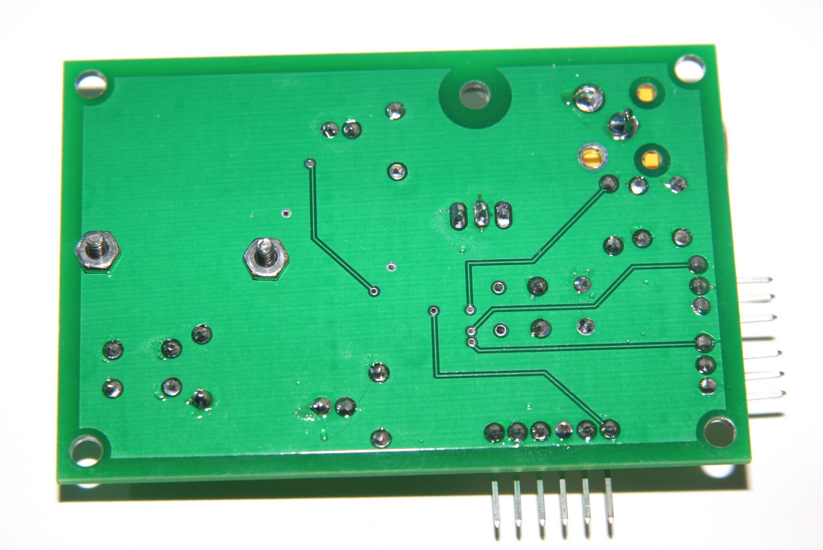
Bottom of board with mini nuts holding the joystick in place.
My first attempt of soldering the surface mount joystick in place went quite well.  Afterwards, I ohm'ed everything out and everything was working as it should.  The mounting holes were a little off so I decided to remount the component.  Bad idea!  I ended up ripping a pad off of the joystick.  But luckily I have one spare, and now I get to take the broken one apart!

Exploded SparkFun Joystick (PN COM-09426)
The sliding part of the joystick consists of two pieces of plastic, one for X and the other for Y.  These pieces of plastic have the contact on it to touch against the the center PWB.  Simply put, there are two linear potentiometers that make up this joystick.

Here is the link to the joystick on SparkFun's site. Joystick COM-09426